

G Code PMC 9 Part Programming & Examples
G00.....Rapid Traverse - axis moves at maximum feedrate
G01......Linear Interpolation - axis moves at programmed feedrate
G02.....Circular Interpolation, Clockwise
G03.....Circular Interpolation, Counter Clockwise
G04.....Program Dwell
G06.....Sinusoidal Interpolation Loop
G10......Inserted Chamfer or Radius
G17.......XY Plane Select for Circular Interpolation & Cutter Radius Compensation
G18.......ZX Plane Select for Circular Interpolation & Cutter Radius Compensation
G19.......YZ Plane Select for Circular Interpolation & Cutter Radius Compensation
G21.......G01 Mode with Sharp Corner Activation, Deceleration between Moves
G22.......G02 Mode with Sharp Corner Activation, Deceleration between Moves
G23.......G03 Mode with Sharp Corner Activation, Deceleration between Moves
G34.......Counter Clockwise Milled Rectangular Cavity
G35.......Clockwise Milled Rectangular Cavity
G36.......Milled Circular Cavity
G40.......Cancel Cutter Radius Compensation
G41........Activate Cutter Radius Compensation, Right of Path
G42.......Activate Cutter Radius Compensation, Left of Path
G43.......Special Cutter Radius Compensation Entry Move
G49.......Counter Clockwise Rectangular Pattern
G50.......Clockwise Rectangular Pattern
G51........Probe Measuring Cycle
G55.......Part Rotation
G56.......Cancel Part Rotation
G57........Part Scaling
G58.......Cancel Part Scaling
G67........Absolute Coordinate Position Programming for Current Block
G68.......Incremental Coordinate Position Programming for Current Block
G69.......Machine Absolute Coordinate Position Programming for Current Block
G70.......Inch Programming
G71........Metric Programming
G80......Cancel Canned Cycle
G81.......Standard Drilling Cycle
G82......Spot Facing - Drilling Cycle with Dwell
G83......Deep Hole Drilling Cycle
G84......Tapping Cycle
G85......Boring Cycle with Dwell, Feedrate Return
G86......Boring Cycle with Spindle Stop, Rapid Return
G87......Case Boring Cycle
G88.....Bore with Dwell, Spindle Orient, Rapid Return
G89.....Reversed Facing Cycle (Back Boring)
G90.....Absolute Dimension Programming
G91......Incremental Dimension Programming
G92.....Constant Surface Speed Radius and Spindle Speed Specification - Lathe Only
G92.....Program Zero Set = Defines New Program Zero Offset from Machine Home
G93.....Inverse Time Feedrate Programming (1/T)
G94.....Feed per Minute Feedrate Programming (IPM or MMPM)
G95.....Feed per Revolution Feedrate Programming (IPM or MMPM)
G96.....Constant Surface Speed (CSS) Mode Spindle Speed – Lathe Only
G97......Spindle RPM Programming Mode
G98.....Program Zero Set - Defines New Program Zero Offset from Machine Home
G00 Rapid Traverse Positioning
The G00 code sets rapid traverse positioning mode. Subsequent moves are at the maximum feedrate available for the machine.
G00X1.5Z2. ; move at maximum speed to position X1.5, Z2.
X5.6 ; move at maximum speed to position X5.6
G01 Linear Interpolation
The G01 code sets linear interpolation mode. Subsequent moves are in a straight line at the current program feedrate. The feedrate is determined by the last programmed F-code. When a G01 move is executed, the machine moves from its current position to the programmed position in a straight line.
G00XZ ; position to X0 Z0 at max speed
F50 ; set feedrate to 50 IPM
G01X2.5 ; feed to X2.5, Z makes no move;stays at Z0
X1.Z4.6 ; feed to X1., Z4.6
G02 Circular Interpolation, Clockwise
G03 Circular Interpolation, Counter Clockwise
The G02 and G03 commands are used to create circular motion. The G02 specifies a clockwise (CW) direction, and the G03 specifies a counterclockwise (CCW) direction. Motion is at the current feedrate.
The starting point is the current axis position when this block begins execution. The coordinates in the G02 or G03 block specify the arc endpoint. There are two different methods for defining the arc:
- The radius of the move may be programmed with an R-code, and the control automatically calculates the arc center.
- The arc center may be programmed and the control calculates the arc radius.
Method 1 is generally the simpler to program, but either method is valid.
Radius Programming:
Radius programming of a circular move is accomplished with an R-code. The circular move is between 0° and 180° if the specified R value is positive, or between 180° and 360° if the specified R value is negative. If the absolute value of the R value specified is less than one-half the distance between the move start and end points (i.e., the chord), the R value is adjusted so a 180° move is made (the R value is equal one-half the chord). If no R is specified, the last value of R is used.
G00X0Y0 ; position to location X0 Y0 at max speed
F10 ; set feedrate of 10 IPM
G02X2.Y0R1. ; move in CW direction to X2. Y0 at a radius of 1.this would result in a 180° move
G03X1.Y1. ; move in CCW direction to X1. Y1. at a radius of 1. (last programmed R-code); this would result in a 90° move.
X0Y0; move in CCW direction to X0 Y0 at a radius of 1. the G03 and the last programmed R-code are modal. The move : made would be 90°.
X1.Y1.R-1.; move in CCW direction to X1 Y1 at a radius of 1.; this
; would result in a 270° move.
G01X1.Y1. ; move in linear mode to X1. Y1.
NOTE: Special care must be taken when programming with the R-code, as the control always makes some type of circular move to the desired endpoint, even if a programming mistake is made and the wrong coordinates or the wrong radius is specified.
Arc Center Programming:
The I and J codes are used in circular interpolation as arc center offsets (in the XY plane). The offsets are unsigned, incremental axis values defining the coordinates of the center of the arc with respect to the starting point of the arc. The programmed arc must not cross a quadrant boundary or the error message INVALID ARC is displayed (the arc center is used as the origin for defining quadrants). If an arc center offset value is zero, it need not be programmed. The calculated arc endpoint based on the programmed I and J codes must be located on the arc within an allowable tolerance or the error message INVALID ARC is displayed.

The diagram illustrates the usage of the I and J codes in arc center programming of a G02 command. The I-code specifies the arc offset in the X-axis, and the J-code specifies the arc offset in the Y-axis. Both are unsigned values. The coordinates of the starting point are the endpoint of the preceding block, and the coordinates of the endpoint are the coordinates in the G02 block.
Assume a starting point of X20 Y30, and the desired move is a CW 90° arc of 10." radius to the location X30. Y20. The center of the arc is at X20. Y20. The distance from the starting point to the center is 0.0" along the X-axis, so the I-code is 0. The distance from the start point to the center along the Y-axis is -10", so the J-code is 10. The programmed block would then be:
G02 X20. Y30. I0 J10.

The I-code can be omitted, as the control assumes a value of zero if none is given.
G04 Program Dwell
The G04 code causes a pause in program execution for a time specified in seconds (or spindle revolutions) by an X or F coordinate in the same block. The X and F codes are interchangeable. No operator interaction is required to continue program execution.
The format of the G04 command is:
G04X5.

This would cause a 5 second delay in program execution.
G06 Sinusoidal Interpolation Loop
This code was developed for a special application, and would not normally be used by a machining center or lathe.
The G06 code was designed for a 2-axis configuration to run both axes in a continuous loop following a sinusoidal pattern. The purpose is to provide smooth acceleration and deceleration during move reversals, yet still allow high speed motion.
The format of the G06 command is:
G06 X Y
Where X and Y specify the endpoint of the pattern.
The position of X and Y before the G06 block is executed represents the start of the pattern. X and Y move to the endpoints specified, then return to the starting point, then back to end endpoint, and so on, indefinitely. The G06 code requires that the PMI program have the variable @RUNG6 used to control the looping. When @RUNG6 is set false, the looping stops the next time the start position is reached.
A key feature of this interpolation method is that during the reversal of direction for X and Y, there is no round-cornering or stopping of either axis – a continuous, smooth motion is maintained.
G10 Inserted Arc or Chamfer
The G10 code provides a simplified means to add an arc or chamfer move between two linear moves, without requiring the programmer to calculate the arc/chamfer endpoints. For arc insertions, the arc is inserted such that the start and end positions are tangent to the programmed lines.
Programmed along with either an L or R code, G10 inserts a chamfer (L) or radius (R) between two linear moves. Both moves must be linear. The second move may also have a G10 if another insertion is desired.
G00X0Y0 ;Rapid move to 0,0
G01F50G10Y5R.5;Move 1 - inserted .5" arc
G10X10Y0L.25;Move 2 - inserted .25" chamfer
G10Y5R.5;Move 3 - inserted .5" arc
X5 ;Move 4
M30

Move 1 does a linear move from X0Y0 to X0Y4.1909 and then does a clockwise arc inserted move to blend with move 2.This arc has a radius of .5" and ends at X.7236Y4.6382.
Move 2 starts at this point and does a linear move to X9.7764Y.1118 and then does a linear .25" chamfer move to X10Y.25.
Move 3 does a linear move to X10Y4.5 and then does a counter-clockwise .5" arc to X9.5Y5.
Move 4 is a linear move to X5Y5.
G17 Plane Selection XY
G18 Plane Selection ZX
G19 Plane Selection YZ
G17, G18, and G19 define the active plane for programming of arcs and the use of cutter radius compensation. For machining centers, the G17 plane is active by default; for lathes it is G19.
For circular contouring modes, as well as cutter compensation offsets, directions are determined by the 'right hand rule'. This means that determination of clockwise (CW) and counter- clockwise (CCW) as well as right/left must be made when viewing the axes in the correct orientation, as defined below:


G21 G01 Mode with Sharp Corner Activation, Deceleration between Moves
G22 G02 Mode with Sharp Corner Activation, Deceleration between Moves
G23 G03 Mode with Sharp Corner Activation, Deceleration between Moves
G34 Counter Closckwise Milled Rectangular Cavity
G35 Clockwise Milled Rectangular Cavity
G36 Milled Circular Cavity
G40 Cancel Cutter Radius Compensation
G41 Activate Cutter Radius Compensation, Right of Path
G42 Activate Cutter Radius Compensation, Left of Path
G43 Special Cutter Radius Compensation Entry Move
The cutter compensation codes are used to activate and deactivate a feature of the control which permits programming of the actual finished part dimensions, without performing special calculations to compensate for cutter radius. When cutter compensation is active, the control automatically compensates for the cutter radius by shifting the tool position relative to the programmed position.
The diameter of the tool is specified in the tool offset table, and activated when a D-code is programmed.
G40 Cancels cutter compensation
G41 Cutter compensation to the left of the tool path
G42 Cutter compensation to the right of the tool path
G43 Special entry mode for cutter compensation initial move
Cutter compensation is inserted by the control in a direction perpendicular to the current direction the tool is moving. Thus, the actual direction of compensation cannot be determined until a move is programmed (the control performs a look-ahead function to determine subsequent move intersections). The direction of compensation is best understood by thinking in terms of the tool position, and looking forward from the tool in the direction of travel. Compensation can then be applied to the left or to the right of this motion.
The G41 code selects cutter compensation left, and G42 selects cutter compensation right. The G40 code cancels cutter compensation. Both linear and circular moves are compensated when G41 or G42 modes are active.
In order to operate correctly, cutter compensation requires that the control "look ahead" in the part program to calculate block intersection points and modify move endpoints accordingly to avoid gouging the part. Whenever a block intersection occurs where the cutter is on the outside of two moves which create an angle of less than 70°, an arc move is inserted by the control to minimize the cutter path.
T01D01; select tool number 1, offset number 1
G00XY ; position to X0 Y0
G41; activate cutter compensation left
G01X1.; first a move is made to compensate for the cutter radius,then the head is lowered, and finally a move is made along the X-axis. The final endpoint is determined by the cutter radius.
Y1.; continue milling a square pattern
X0
Y0
G40; cancel cutter compensation
M30; end program


G49 Counter Clockwise Rectangular Pattern
G50 Clockwise Rectangular Pattern
G51 Probe Measuring Cycle
G55 Part Rotation
G56 Cancel Part Rotation
G55 Turns on part program rotation
G56 Turns off part program rotation
The G55 code is programmed with an R code (in degrees) to activate and define the angle for part rotation.
While this is active, all endpoints in the active plane (G17-G19) are rotated from Program Zero by the angle defined by the R code.
G00X5Y5 ;move 1
G55R45;turn on rotation with an angle of 45 deg
G01F50X10 ;move 2
Y10 ;move 3
G56 ;turn off rotation
M30

Move 1 to X5Y5.
Move 2 to X7.0711 Y7.0711 ( X10Y10 rotated 45 deg)
Move 3 to X5 Y14.1421
G57 Part Scaling
G58 Cancel Part Scaling
G57 Turns on program scaling
G58 Turns off program scaling
The G57 code is programmed with an R code to scale all program dimensions in the active plane by the value in the R code.
G00X5Y5 ;move 1
G57R.5;turn on scaling with a factor of .5
G01X6 ;move 2
Y10 ;move 3
X8Y12 ;move 4
G58 ;turn off scaling

Move 1 is a positioning move to X5 Y5
Move 2 is a move to X3 Y2.5 (both axis positions are scaled even though only one is programmed) Both axes should be programmed on the first move after scaling is turned on.
Move 3 is to X3 Y5
Move 4 is to X4 Y6
G67 Absolute Coordinate Position Programming for Current Block
G68 Incremental Coordinate Position Programming for Current Block
G69 Machine Absolute Coordinate Position Programming for Current Block
Although valid at any point in a part program, the G67-G69 non-modal codes were specifically developed to assist in writing APP cycles without destroying any modal codes prior to programming of a cycle. They permit a "one-block" deviation from the current programming mode without having to restore the original mode.
G67 ABSOLUTE BLOCK
This code functions similar to a G90 block in setting of absolute programming mode format. Any valid axis letter code programmed in this block is interpreted as absolute data, regardless of the modal status of G90/G91 prior to this block. Subsequent blocks return to the G90/G91 status that was in effect prior to this block's execution.
G68 INCREMENTAL BLOCK
This code functions similar to a G91 block in setting of incremental programming mode format. Any valid axis letter code programmed in this block is interpreted as incremental data to be added to the last programmed position, regardless of the modal status of G90/G91 prior to this block. Subsequent blocks return to the G90/G91 status that was in effect prior to this block's execution.
G69 MACHINE ABSOLUTE BLOCK
This code has no equivalent modal code. This block permits programming axis coordinates to a specific location in the machine coordinate system, ignoring any coordinate system offsets that may be in effect. Any valid axis letter code programmed in this block are interpreted as absolute data from machine zero, regardless of the modal status of G90/G91, or any zero offsets prior to this block. Subsequent blocks return to the G90/G91 status, and program coordinate system that was in effect prior to this block's execution.
G70 Inch Programming
Programs are in inches.
G71 Metric Programming
Programs are in millimeters.
G80 Cancel Canned Cycle
The G80 series of codes are used to simplify the programming typical drilling routines by combining several programmed moves into one block of information. These cycles are provided by the OEM with the machine, and may be modified to suit particular applications. This document describes the standard usage of these cycles for the SERIES 8.
The codes G81-G89 are the actual canned cycles. These codes are modal, which means that when one of these codes is used, for example 'G81', then subsequent blocks continue to execute the G81 cycle, until it is canceled by a G80. The G80 code cancels any of the canned cycles.
The drilling canned cycle codes follow a basic pattern as follows:
- Position the XY axes to a location (if the machine has rotary axes, they are positioned also)
- Move the Z axis as needed to perform the desired
- The "R-plane" is typically a clearance position for the Z
- The "Z-plane" is typically the final depth of the drilling operation
Note: Once programmed in a cycle, the R-plane and Z-plane values are saved by the system and are used as defaults for subsequent drilling cycles if these codes are omitted.
G81 Standard Drilling Cycle
Format: G81 X- Y- Z- A- R- F- D- M- S-
The D-code may be used to specify the tool length offset to use for this drill cycle.
The M-code may be used to turn on the spindle (M03=clockwise, M04=counter-clockwise).
The S-code may be used to specify the spindle speed.
Sequence description:
- Move to the position specified for XYA at the rapid traverse rate.
- Move the Z-axis to the R-code position (R-plane) at the rapid traverse rate.
- Move the Z-axis to the Z-code position (Z-plane) at the programmed feed (F-code).
- Move the Z-axis back to the R-plane at the rapid traverse rate.

G82 Spot Facing - Drilling Cycle with Dwell
Similar to G81 cycle, except that there is an added dwell at the bottom of the drill stroke.
Format: G82 X- Y- Z- A- R- P- F-
Sequence description:
- Move to the position specified for XYA at the rapid traverse rate.
- Move the Z-axis to the R-code position (R-plane) at the rapid traverse rate.
- Move the Z-axis to the Z-code position (Z-plane) at the programmed feed (F-code).
- Dwell by the time specified by the P-code in seconds
- Move the Z-axis back to the R-plane at the rapid traverse rate.

G83 Deep Hole Drilling Cycle
Similar to G81 cycle, except that the final depth is reach by several drill strokes, each one getting deeper until the final depth is reached. Every retract stroke comes completely out of the hole to the R-plane position; every drilling stroke rapids to a height of 0.050" above the last drilled depth, then it feeds to the new depth.
Format: G83 X- Y- Z- A- R- I- J- F-
Sequence description:
- Move to the position specified for XYA at the rapid traverse rate.
- Move the Z-axis to the R-code position (R-plane) at the rapid traverse rate.
- Move the Z-axis to the position defined by the I-code at the programmed feed, then retract the Z-axis to the R-plane at the rapid traverse rate.
- Move the Z-axis down to the first peck level I + J at programmed feed, then retract the Z-axis to the R-plane at the rapid traverse rate.
- Repeat feeding the Z-axis in successive pecks to its last down position plus the peck increment (J), until the final programmed depth (Z) is reached; then retract the Z-axis to the R-plane at rapid traverse.
NOTE: The value of the I-code (initial drill depth) is an absolute Z-axis position; the value of the J-code (pecking increment) is an unsigned incremental value for each subsequent drill stroke.

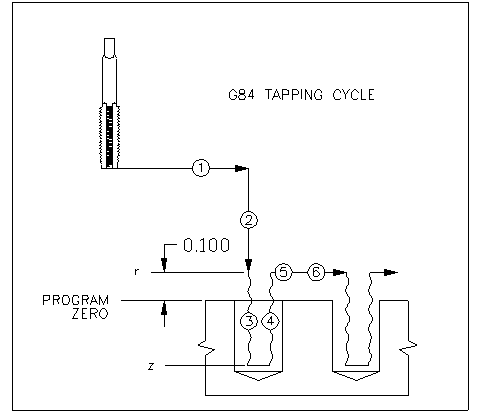
G84 Tapping Cycle
The G84 code is used for tapping operations. For Monarch machines with air tapping capability, this cycle may be operated in a special mode where the Z-axis servo is uncoupled from the slide. (See M73, M74 codes) For other systems, this is a servo tapping cycle where the Z-axis position is synchronized to spindle rotation.
Format: G84 X- Y- Z- A- R- K-
Sequence description:
- Move to the position specified for XYA at the rapid traverse rate.
- Move the Z-axis to the R-code position (R-plane) at the rapid traverse rate.
- Move the Z-axis to the Z-code position, synchronized to the spindle rotation, based on the programmed thread lead (K-code). The feedrate of the Z-axis move is a function of the spindle RPM and the thread lead.
- Reverse the rotation of the spindle, and retract the Z-axis to the R-plane, synchronized to the spindle rotation, based on the programmed thread lead (K-code).
- Run spindle in the original direction it was turning.
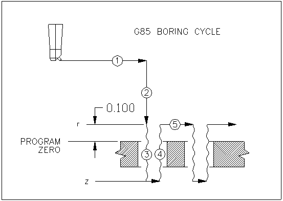
G85 Boring Cycle with Dwell, Feedrate Return
Similar to G82 cycle, except that the retract to the R-plane is made at the programmed feedrate instead of the rapid traverse rate.
Format: G85 X- Y- Z- A- R- P- F- D- M- S-
The D-code may be used to specify the tool length offset to use for this drill cycle.
The S-code may be used to specify the spindle speed.
he M-code may be used to turn on the spindle (M03=clockwise, M04=counter-clockwise).
Sequence description:
- Move to the position specified for XYA at the rapid traverse rate.
- Move the Z-axis to the R-code position (R-plane) at the rapid traverse rate.
- Move the Z-axis to the Z-code position (Z-plane) at the programmed feed (F-code).
- Dwell by the time specified by the P-code in seconds, then move the Z-axis back to the R-plane at the programmed feed.
G86 Boring Cycle with Spindle Stop, Rapid Return
Similar to G85 cycle, except that at the bottom of the drill stroke the spindle is stopped prior to retracting the Z axis.
Format: G86 X- Y- Z- A- R- P- F- D- M- S-
The D-code may be used to specify the tool length offset to use for this drill cycle.
The S-code may be used to specify the spindle speed.
The M-code may be used to turn on the spindle (M03=clockwise, M04=counter-clockwise).
Sequence description:
- Move to the position specified for XYA at the rapid traverse rate.
- Move the Z-axis to the R-code position (R-plane) at the rapid traverse rate.
- Move the Z-axis to the Z-code position (Z-plane) at the programmed feed (F-code).
- Dwell by the time specified by the P-code in seconds; stop the spindle; then move the Z-axis back to the R-plane at the programmed feed.
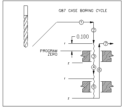
G87 Case Boring Cycle
Similar to G81 cycle, except that the Z-axis does not retract to the R-plane after reaching the Z-plane. It is designed so that subsequent layers may be drilled without requiring full retract of the Z-axis, but allowing rapid positioning from one layer to the next.
Format: G87 X- Y- Z- A- R- F- D- M- S-
The D-code may be used to specify the tool length offset to use for this drill cycle.
The S-code may be used to specify the spindle speed.
The M-code may be used to turn on the spindle (M03=clockwise, M04=counter-clockwise).
Sequence description:
- (first block) Move to the position specified for XYA at the rapid traverse rate.
- (first block) Move the Z-axis to the R-code position (R-plane) at the rapid traverse rate.
- (first block) Move the Z-axis to the Z-code position (Z-plane) at the programmed feed (F-code).
- (second block) Move to new R-code at rapid traverse rate.
- (second block) Move to Z-position at the programmed feed.
G87 X5. Y6. R3.5 Z3.0 F20. ; drill first hole at X5 Y6, to depth of 3.0" (no retract)
R2.0 Z1.0; drill second hole by moving at rapid to Z2.0, then feeding to position of Z1.0
G88 Bore with Dewll, Spindle Orient, Rapid Return
Similar to G86 cycle, except that when the spindle is stopped prior to retracting the Z-axis, the spindle is first oriented and XY are moved to avoid the boring bar touching the wall of the hole during retract.
Format: G88 X- Y- Z- A- R- F- D- I- J- M- S-
The D-code may be used to specify the tool length offset to use for this drill cycle.
The S-code may be used to specify the spindle speed.
The M-code may be used to turn on the spindle (M03=clockwise, M04=counter-clockwise).
Sequence description:
- Move to the position specified for XYA at the rapid traverse rate.
- Move the Z-axis to the R-code position (R-plane) at the rapid traverse rate.
- Move the Z-axis to the Z-code position (Z-plane) at the programmed feed (F-code).
- Dwell by the time specified by the P-code in seconds; stop the spindle, and orient it at 0 degrees.
- Move the XY axes by the values specified in I & J, respectively
- Move the Z-axis back to the R-plane at the programmed feed.

G89 Reversed Facing Cycle (Back Boring)
This cycle is designed to bore 'from the bottom up' by positioning the boring tool through a pre-drilled hole to start with, then bore in the positive direction. The spindle is oriented and shifted off-center to allow passing the boring tool through the hole.
Format: G89 X- Y- Z- A- R- F- D- I- J- M- S-
The D-code may be used to specify the tool length offset to use for this drill cycle.
The S-code may be used to specify the spindle speed.
The M-code may be used to turn on the spindle (M03=clockwise, M04=counter-clockwise).
Sequence description:
- Move to the position specified for XYA at the rapid traverse rate.
- Stop and orient the spindle; move the Z-axis to the clearance position at the rapid traverse rate.
- Shift the XY axes off center by the amount in I and J.
- Rapid the Z-axis to the R-plane.
- Shift XY back to center of hole and turn on spindle.
- Feed Z to the Z-plane (positive direction)
- Dwell by the time specified by the P-code in seconds
- Return the Z-axis to the R-plane at the programmed feed.
- Stop the spindle, and orient it at 0 degrees; move the XY axes by the values specified in I & J, respectively.
- Move the Z-axis back to the original starting level at rapid traverse.
- Shift the XY axes back to center position.
- Start the spindle.

G90 Absolute Dimension Programming
G91 Incremental Dimension Programming
The G90 and G91 codes determine how X and Z coordinate information in the part program are interpreted.
In G90 (absolute) mode, the program coordinates specify the desired axis position as an absolute position from program zero:
G90
X1.5Z1.5

The machine moves to the position X1.5 Z1.5, and these values are displayed as the axis position on the Production Page.
In G91 (incremental) mode, the program coordinates specify the desired axis position as an incremental distance from the last programmed axis position:
G90
X1.5Z1.5
G91
X.5
X-.75

The first two blocks move the machine to the position X1.5 Z1.5, as described above. The G91 block then sets up incremental mode. The block "X.5" then moves X a distance of .5 to 2.0. The X-axis displayed position is2.0. The last block, "X-.75", moves X in the minus direction .75 to 1.25.
Both G90 and G91 are modal codes. Upon system startup or a Control Reset, G90 mode is active.
G90 - Absolute Mode

G91 - Incremental Mode

G92 Program Zero Set = Defines New Program Zero Offset from Machine Home
The G92 and G98 codes function the same. Their purpose is to define a new part program zero position, based on the current position of the axes.
G92 X- Y- Z- A-
The current program position of any axis programmed is set to the value specified on this block. One or more axes may be programmed in the G92 or G98 block. Only the axes programmed have their zero position changed. An M30 end of program code or a CONTROL RESET cancels the G92/G98 offset.
G00 X5.; position the X-axis to 5.000"
G92 X3.5 ; define this position to now be 3.500"
G00 X5; move to X position 5.000"(the X-axis moves 1.5", from 3.5" ; to 5.0")
G93 Inverse Time Feedrate Programming (1/T)
Program moves can be made in what is called 'inverse time mode' where the time for the program move is specified, not the feedrate. This is programmed with a G93 code. G93 is a modal code, and all subsequent feedrate commands are interpreted as inverse time until a G94 or G95 is programmed, or there is a CONTROL RESET.
In G93 mode, the feedrate is specified with an F-code in inverse time for the programmed move to complete in minutes:
G00 X0; position X to 0.0
G93 F2; set inverse time feedrate of ½ minute (30 seconds)
G01 X10.; move X to a position of 10.

The G01 move of 10 inches is made in the time specified of 30 seconds ( ½minute), which is equivalent to 20 inches per minute
Inverse time programming is typically used when moving rotary axes, either independently or along with other linear axes.
G94 Feed per Minute Feedrate Programming (IPM or MMPM)
For most milling applications, the feedrate is programmed in inches per minute, or millimeters per minute depending on the status of inch/metric programming. This is G94 mode, and is active as the default method of setting the feedrate.
G00 X0
G01 X10. F20.
The G01 moves the X-axis a total of 10 inches, at a rate of 20 inches per minute.The total time of the move would be 30 seconds.
Note: When running in G94 mode, varying the spindle speed also varies the feedrate of the programmed axes. Axes are limited by the maximum capable speed as defined in the Parameter Editor.
G95 Feed per Revolution Feedrate Programming (IPM or MMPM)
For most turning applications, the feedrate is programmed in inches per revolution, or millimeters per revolution depending on the status of inch/metric programming. The 'revolution' refers to the main spindle of the machine. The feedrate specifies how far the axis moves for one revolution of the spindle. In order for this type of feedrate programming to be valid, there must be spindle speed feedback to the CNC. In order to activate this mode, a G95 must be programmed. When G95 is programmed, the spindle must be turning in order to generate a programmed move (other than G00).
G00 X0
M03 S500 ; turn spindle on at 500 RPM
G95 ; set IPR programming mode
G01 X10. F.02

The G01 block moves the X-axis a total of 10 inches at the rate of .020" per revolution of the spindle. With a spindle speed of 500 RPM, the speed of the X-axis is 100 inches per minute.

500 RPM * 0.020 IPR = 100 IPM
G92 Constant Surface Speed Radius and Spindle Speed Specification - Lathe Only
G96 Constant Surface Speed (CSS) Mode Spindle Speed - Lathe Only
G97 Spindle RPM Programming Mode
Constant surface speed is a feature used on lathe systems to automatically vary the spindle speed based on the position of the X-axis. As the X-axis moves from a larger diameter to a smaller diameter, it is generally desirable to increase the spindle speed accordingly to maintain a constant surface feedrate of the tool in contact with the part.
Standard programming of the spindle is in G97 mode, which is the default. The desired spindle speed is programmed directly as an S-code.
G97
G97 mode is active upon power up, after a control reset, or at the end of program. It is not normally required to program a G97 unless CSS mode has been activated and then needs to be canceled.
CSS mode is set with the G96 code. The G92 block is used to set parameters for CSS mode:
G92 R- S-
R - specifies the radius at the current X axis position.
S - specifies the max spindle speed while CSS is active (note that the overall maximum spindle speed is limited by the value set in the Parameter Editor).
G96 S-
S - specifies surface feet per minute (inch mode) or surface meters per minute (metric mode).
When CSS mode (G96) is active, the S-code may be programmed on subsequent blocks to change the surface speed without re-programming the G96 code.
Temporary override of CSS mode
M59
In CSS mode, M59 temporarily disables CSS. Commanded spindle speed remains at its last value regardless of X axis position or any new S code.
M58
Cancels M59. CSS is re-enabled.
For instance, if the tool is 4 inches from the center, the maximum speed of the spindle in the present range is 600 RPM, the desired surface speed is 300 SFM, and the operator wishes to do a facing cut through the center of rotation, the program would be:

G00X8.Z0 ; move to diameter of 8 inches
G95F.005 ; sets feedrate of 0.01 IPM
G92R4.S600 ; sets radius as 4 inches and limits RPM to 600
G96S300; sets CSS mode at 300 SFM (initial RPM is 143 RPM)
G01X-.01 ; moves X axis 0.01 inches past center
G01Z.1 ; move Z away from part
G97; return to RPM spindle speed programming mode

The initial RPM can be calculated as follows:

Circumference of part at 4" Radius
2*pi*4" = 25.133" = 2.094'

(300 ft/min) / (2.094 ft/rev) = 143 RPM

As the tool moves toward the center, the spindle speed increases until,at a radius of 0.9549” (1.9099” diameter) it reaches its maximum of 600 RPM.It maintains this speed for the remainder of the move.
NOTE: In order to use RPM & CSS mode, PMI must use the variable @LCRPM as the commanded spindle speed instead of @SCODE.
G98 Program Zero Set - Defines New Program Zero Offset from Machine Home
The G92 and G98 codes function the same. Their purpose is to define a new part program zero position, based on the current position of the axes.
G92 X- Y- Z- A-
The current program position of any axis programmed is set to the value specified on this block. One or more axes may be programmed in the G92 or G98 block. Only the axes programmed have their zero position changed. An M30 end of program code or a CONTROL RESET cancels the G92/G98 offset.
G00 X5.; position the X-axis to 5.000"
G92 X3.5 ; define this position to now be 3.500"
G00 X5; move to X position 5.000"(the X-axis moves 1.5", from 3.5" ; to 5.0")